
In high-frequency data cable manufacturing, insulation concentricity is not a cosmetic metric—it directly affects impedance stability, signal integrity, insertion loss, and return loss. As data rates increase and tolerance margins tighten, maintaining over 95% insulation concentricity becomes a baseline requirement rather than a premium feature.
However, many manufacturers struggle to achieve this level consistently in mass production. The problem is rarely a single parameter error. In reality, concentricity loss is the result of mechanical alignment, material behavior, and process stability interacting simultaneously.
This article explains how experienced cable manufacturers maintain insulation concentricity above 95% in high-frequency data cable production—and what typically goes wrong when they don’t.
Why Insulation Concentricity Matters More in High-Frequency Cables
For low-frequency or power cables, minor eccentricity may have limited impact. In high-frequency data cables (USB, HDMI, LAN, coaxial, automotive data cables), the situation is very different.
Poor insulation concentricity leads to:
Impedance fluctuation along the cable length
Increased signal reflection (return loss degradation)
Higher attenuation and unstable transmission performance
Failure in eye-diagram and TDR testing
In short, eccentric insulation equals unstable electrical performance, even if the outer diameter remains within tolerance.
1. Mechanical Alignment Is the Foundation of High Concentricity
Die and tip alignment is not “set once and forget”
The extrusion die and tip alignment directly defines insulation concentricity. Even a small angular deviation can cause insulation to drift to one side under melt pressure.
Key best practices include:
Precision centering of die and tip before every production run
Using dial indicators or laser alignment tools instead of visual judgment
Verifying alignment after die changes or maintenance
Many concentricity problems are mistakenly blamed on material or operators, when the real issue is micron-level mechanical misalignment.
Pay-off and take-up alignment matters more than expected
If the conductor enters the crosshead off-center due to:
Misaligned pay-off
Uneven tension
Conductor vibration
the insulation will follow that offset, no matter how well the die is centered.
Experienced factories treat conductor entry alignment as part of concentricity control, not a separate setup task.
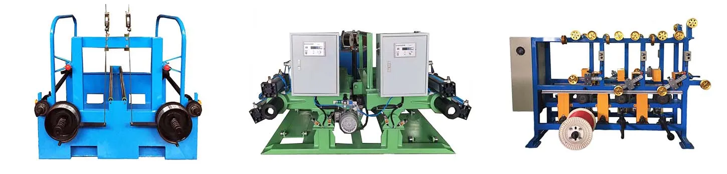
2. Stable Conductor Tension Prevents Insulation Drift
Tension fluctuation = moving conductor centerline
In high-frequency cable extrusion, the conductor must remain perfectly centered inside the insulation melt flow. Any tension fluctuation causes the conductor to oscillate, resulting in eccentric insulation.
Common causes of tension instability:
Mechanical brake systems with delayed response
Inconsistent pay-off inertia
Worn dancer mechanisms
Practical tension control strategies
Use closed-loop tension control systems instead of manual brakes
Minimize sudden speed changes during startup and stop
Match pay-off and extrusion line acceleration profiles
Stable tension does not just improve concentricity—it also reduces surface defects and conductor deformation.
3. Melt Flow Stability Is Critical at High Line Speeds
Uneven melt pressure pushes insulation off-center
High-frequency data cables often require:
Thin insulation walls
Tight OD tolerances
High extrusion speeds
Under these conditions, even slight melt flow imbalance can push insulation to one side.
Key contributors to unstable melt flow include:
Worn or contaminated extrusion screws
Inconsistent temperature zoning
Poor material plasticization
Process control recommendations
Maintain uniform temperature gradients along the barrel
Avoid aggressive screw speeds that cause pressure pulsation
Clean screws and flow channels regularly to prevent asymmetrical flow
A smooth, stable melt flow allows the insulation to form evenly around the conductor instead of “chasing” it.
4. Material Behavior Must Be Matched to Process Design
Not all insulation compounds behave the same
High-frequency cables often use:
Foamed PE
Solid PE
FEP / PFA
Low-dielectric PVC or TPU
Each material responds differently to shear, temperature, and pressure. Using generic extrusion settings across different compounds is a common mistake.
Material-specific optimization
Foamed materials require especially stable pressure control
Fluoropolymers demand precise temperature uniformity
Moisture-sensitive compounds must be properly dried
Manufacturers that consistently achieve >95% concentricity treat material behavior as a process variable, not a constant.
5. Cooling Design Directly Affects Final Concentricity
Early-stage cooling locks in eccentricity
Once the insulation exits the die, its position is still adjustable—until cooling begins. Uneven or premature cooling will freeze eccentricity into the cable.
Best practices include:
Symmetrical cooling water flow around the cable
Avoiding cold shock immediately after extrusion
Proper sizing of cooling trough length and temperature zones
In high-speed lines, poorly designed cooling systems are a hidden cause of concentricity loss.
6. Measurement and Feedback Close the Loop
You can’t control what you don’t measure
Factories that maintain high concentricity do not rely solely on end-of-line inspection. They implement:
Online diameter and concentricity monitoring
Frequent cross-section sampling
Data logging tied to process parameters
When concentricity starts drifting, corrective action is taken immediately—not after a batch fails testing.
Final Thoughts: 95% Concentricity Is a System Outcome
Maintaining insulation concentricity above 95% in high-frequency data cable production is not about a single machine upgrade or one skilled operator. It is the result of system-level discipline:
Precise mechanical alignment
Stable conductor tension
Controlled melt flow
Material-specific process design
Balanced cooling
Continuous measurement and feedback
When these elements work together, high concentricity becomes repeatable, not accidental.
Explore the complete cable manufacturing system:
→ Cable Manufacturing Process & Equipment Guide