
USB and Type-C cables appear deceptively simple—yet their internal architecture makes them among the most interference-sensitive consumer cables ever engineered. As signal rates surge from USB 2.0’s 480 Mbps to USB 3.2/4.0’s 20–40 Gbps and Thunderbolt 4’s 40 Gbps, manufacturers face an escalating challenge: maintaining consistent shielding performance across every meter of cable, even under bending, temperature fluctuations, and high-volume production.
Shielding isn’t merely an engineering checkbox—it directly impacts product yield (reducing rework by 20–30% when optimized), charging stability (eliminating PD negotiation failures), and post-sales costs (cutting return rates by up to 40%). Below is a comprehensive technical roadmap covering shielding structures, material science, process control, and equipment selection—with natural internal links to solutions that solve real production pain points.
1. Why Shielding Matters More for Modern USB/Type-C Cables
- Eye-diagram collapse (leading to bit errors in data transmission)
- Crosstalk between differential pairs (degrading signal integrity)
- EMI leakage (especially critical for cables used in medical devices, industrial controls, or aerospace)
- Inconsistent impedance (causing signal reflections)
- Packet loss at high data rates (e.g., 4K video streaming or external SSD transfers)
- Charging “dropout” or unstable Power Delivery (PD) negotiation (frustrating end-users)
Unlike traditional cables, high-speed USB/Type-C cables rarely fail due to conductor breakage. The primary culprit? Drifting shielding uniformity—including braid density inconsistencies, foil overlap gaps, and concentricity errors—over long production runs. This is why modern Type-C manufacturers no longer rely on single-layer shielding (foil or braid alone); they integrate multi-layer designs, each serving a distinct EMI mitigation function.
2. Understanding Shielding Structures for USB/Type-C Cables
Shielding design scales with cable performance requirements. Below is the industry-standard shielding stack, from entry-level USB 2.0 to premium USB 4.0/Thunderbolt 4:
Level 1: Spiral Foil (Aluminum / AL-Mg Alloy)
- Foil overlap: 15–25% (standard for USB 2.0/3.0; 25–35% for USB 3.2/4.0)
- Tension uniformity (±5% variation max)
- Wrinkle control (no creases that create micro-gaps)
- Tape path stability during high-speed wrapping (≥600 RPM)
Level 2: Braiding (Tinned Copper / CCA / AL-Mg Alloy)
- Braid angle (35°–55° for optimal EMI/flexibility balance)
- Carrier speed synchronization (±2 RPM tolerance)
- Actual coverage (not just theoretical—measured via optical inspection)
- Strand tension (uniform across all carriers)
- Roundness retention after extrusion (no flattening)
Level 3: Secondary Foil or Drain Wire
- Stabilize differential pair impedance (±10 Ω tolerance)
- Block EMI leakage through braid gaps
- Reduce crosstalk between data and power lines
Level 4: Outer Sheath Extrusion
- Distorting foil tension (creating gaps)
- Flattening braid strands (reducing coverage)
- Introducing impedance variations
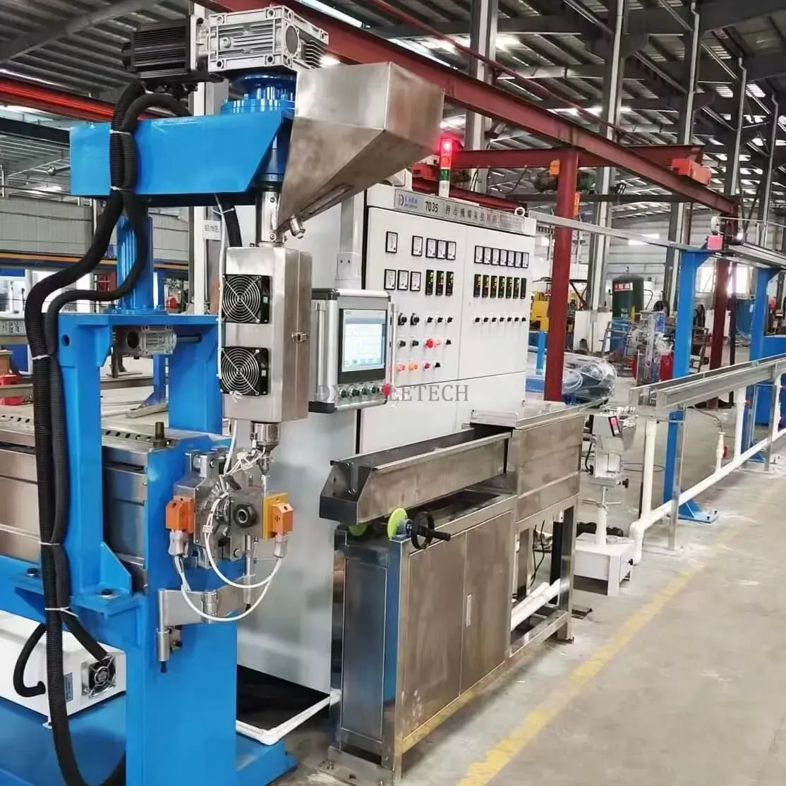
To optimize this step, manufacturers rely on precision extrusion lines with closed-loop control—learn more about configuring these systems in our guide to Extruder Production Lines for High-Speed Cables.
3. Achieving Better Foil Shielding (Technical Deep Dive)
Foil shielding is typically applied via taping machines, where small variations in tension or overlap cause 90% of shielding defects. Below’s how to eliminate these issues:
3.1 Tape Tension Control: The Foundation of Foil Performance
- Over-tension: Foil develops micro-cracks (invisible to inspection but catastrophic for EMI)
- Low tension: Foil floats or lifts during extrusion, creating gaps
- Uneven tension: Overlap oscillates along the cable length (e.g., 15% in one section, 30% in another)
- Closed-loop tension control (real-time feedback adjusts tension within ±2%)
- Magnetic powder brake systems (for consistent resistance)
- Servo-controlled wrap heads (eliminating mechanical drift)
For factories upgrading their taping equipment, our Coiling, Winding & Taping Machines Guide details how to select units optimized for Type-C foil shielding.
3.2 Overlap Stability at High Speed
- Fixed-angle taping heads (prevents angular drift)
- Guide-roller geometry optimization (reduces friction-induced shifting)
- Active tape edge sensors (adjusts position to maintain overlap)
- Foil pre-tension feedback loops (compensates for material stiffness variations)
3.3 Material Selection: Aluminum vs. AL-Mg Alloy
- Resists cracking during tight bends (critical for portable devices)
- Maintains conductivity over the cable’s lifetime (no oxidation-related degradation)
- Has 30% higher tensile strength (supports thinner designs for slim cables)
- Lower weight (ideal for lightweight accessories like laptop chargers)
4. Braiding Quality: What Actually Affects EMI (Myths Debunked)
Most manufacturers fixate on braid coverage percentage—but EMI performance depends on three often-overlooked factors:
4.1 Real Coverage vs. Theoretical Coverage
Theoretical coverage (calculated based on strand count and braid angle) is rarely achieved in practice. Real coverage drops due to:
- Strand “jumping” (caused by inconsistent carrier tension)
- Braid flattening during extrusion (compressing strands into gaps)
- Cable ovalization inside the braider take-up (creating uneven coverage)
To measure real coverage, use optical inspection systems that capture 360° views of the braid—target ≥95% coverage for USB 4.0/Thunderbolt.
4.2 Braid Angle: The EMI/Flexibility Tradeoff
- Higher angles (45°–55°): Better high-frequency shielding (up to 20 dB attenuation at 10 GHz) but reduced flexibility (critical for cables used in foldable devices)
- Lower angles (35°–45°): More flexible (10,000+ bend cycles) but 15–20% weaker EMI protection
4.3 Carrier Stability: The Key to Consistent Braiding
- High-precision bearings (reducing carrier wobble)
- Servo closed-loop control (synchronizes carrier speed to cable movement)
- Auto-lubrication systems (prevents friction-induced drift)
- Anti-shake design (stabilizes the braid head at speeds >1,000 RPM)
For a breakdown of machine specifications, see our Practical Guide: Choosing Foil + Braiding Machines for USB/Type-C Shielding Upgrades.
5. Extrusion and Shield Integrity (The Overlooked Factor)
Extrusion is the final step that makes or breaks shielding performance. It impacts shield integrity in three critical ways:
5.1 Concentricity Drift
If the outer sheath isn’t concentric (±0.02 mm tolerance), braid resistance fluctuates by up to 15%, disrupting differential pair balance. USB 3.2/4.0 cables are extremely sensitive to this—even small deviations cause impedance mismatches.
5.2 Melt Temperature Control
- Too high: Foil softens, causing overlap to shift or tear
- Too low: Voids form under the braid (trapping air that expands during use, creating gaps)
Optimal melt temperatures vary by material (e.g., TPE: 160–180°C; PVC: 140–160°C) and require closed-loop temperature monitoring.
5.3 Cooling Tank Stability
- Gradual cooling zones (3-stage temperature reduction)
- Water flow uniformity (prevents uneven contraction)
- Vacuum sizing (maintains cable roundness during cooling)
To implement these features, explore our Extruder Production Line Guide, which includes case studies of factories that reduced shielding defects by 40% via extrusion optimization.
6. Integrating the Whole Shielding Workflow (Practical Factory Implementation)
The most successful Type-C cable manufacturers standardize their shielding workflow to eliminate variability. Here’s the step-by-step process:
Step 1: Foil Taping (Controlled Tension + Stable Overlap)
- Equipment: Servo-controlled taping machine with closed-loop tension
- Material: AL-Mg foil (25–35% overlap for high-speed cables)
- Quality Check: Inline optical sensor for overlap verification
Step 2: Braiding (Optimized Angle + Real Coverage Measurement)
- Carriers: 16–24 (16 for USB 3.0; 24 for USB 4.0/Thunderbolt)
- Braid Angle: 40°–45° (balance of EMI and flexibility)
- Quality Check: Optical coverage inspection + braid angle measurement
Step 3: Secondary Foil (for USB 3.2/4.0/TB3 Cables)
- Purpose: Enhance high-frequency EMI shielding (10–20 GHz)
- Application: Same taping machine with adjusted tension (lower than primary foil to avoid over-compression)
Step 4: Extrusion (Locking Structure + Concentricity Control)
- Equipment: Precision extruder with laser diameter gauge and vacuum sizing
- Material: TPE or LSZH (low smoke zero halogen) for safety-critical applications
- Quality Check: Concentricity measurement + spark testing (5 kV for insulation integrity)
Step 5: Inline Monitoring (Continuous Defect Detection)
- Diameter laser gauge (monitors outer sheath thickness)
- Capacitance monitor (detects impedance variations)
- Spark tester (identifies insulation breaks that expose shielding)
7. Natural Internal Link Opportunities (Actionable, Not Forced)
- Practical Guide: Choosing Foil + Braiding Machines for USB/Type-C Shielding Upgrades – Learn how to configure equipment for your specific cable grade (USB 3.0 vs. 4.0) and production volume.
- Extruder Production Line Case Studies – See how two factories reduced shielding-related returns by 35% and 40% via extrusion optimization.
- Material Selection Guide: AL-Mg Foil vs. Tinned Copper Braid – Compare performance, cost, and application scenarios for different shielding materials.
Each link leads to a landing page with actionable advice—e.g., the machine guide includes equipment specs, pricing ranges, and vendor recommendations tailored to Type-C production.
Final Thoughts
Better shielding for USB/Type-C cables isn’t about using the most expensive materials or equipment—it’s about consistency. The key takeaways are:
Control foil tension and overlap (the #1 cause of defects)
Optimize braid angle and real coverage (not just theoretical percentages)
Maintain extrusion concentricity and temperature (the final quality lock)
Use closed-loop control and inline monitoring (eliminate human error)
With the right combination of materials, process control, and equipment, Type-C cable shielding becomes not only compliant with USB-IF standards—but stable, repeatable, and scalable. For factories looking to implement these changes, our Practical Guide: Choosing Foil + Braiding Machines for USB/Type-C Shielding Upgrades provides a roadmap to upgrade existing lines or build new ones optimized for high-speed cable production.
Explore the complete cable manufacturing system:
→ Cable Manufacturing Process & Equipment Guide